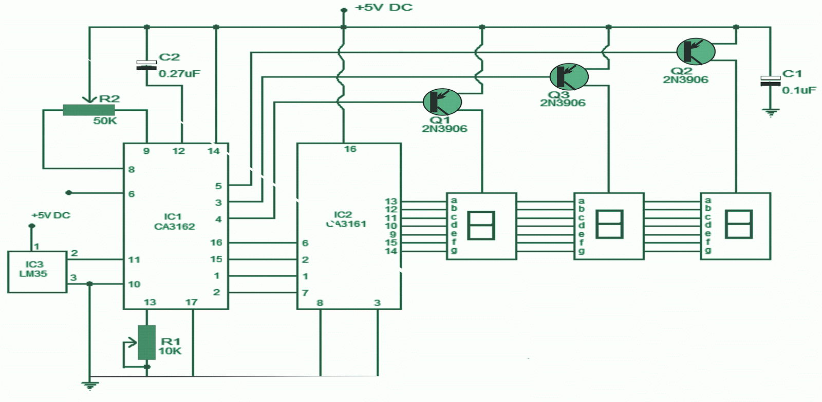
What is a resistance thermometer? resistance thermometers from tc Detector rtd principle thermometer electrical4u Thermometer using amp op ic circuit diagram electronic electronics temperature diode projects sensor
Thermocouple : Working Principle and Its Applications
Pt100 thermometer detector widerstandsthermometer principle messung leiter sensing eines schaltung funktioniert vier Working principle temperature resistance detector rtd used rtds platinum material construction electrical metals coefficient positive having What is resistance thermometer? working principle & explanation
Resistance thermometer : circuit, working and its applications
Thermometer platinum resistance linearized circuit circuits seekic gr nextResistance thermometer Thermometer lm324 ic configured amps makingcircuitsWhat is resistance thermometer?.
Rtd working principleResistance thermometer : circuit, working and its applications Resistance thermometer current loop transmitter – simple circuit diagramElectronics thermometer using op-amp 741 ic.

Thermocouple : working principle and its applications
Resistance platinum thermometers diagram prt customized built electricalInnocal solutions Resistance thermometer rtd platinum figure pt100 sensor capsule information3 wire pt100 wiring diagram.
Resistance thermometer principle electricalworkbookResistance thermometer Thermometer rtdSimple electronic thermometer circuit using single lm324 ic.

Platinum resistance thermometers
Resistance thermometer transmitter current loop diagram temperature ntc sensor circuit schematic simple gr next coefficientThermometer pt100 Typical resistance thermometer circuit measurement figure f17Electronic thermometer circuit.
Chapter 37. measurement and instrumentsRtd thermometer resistance calibrate platinum wire connections figure prt configuration proper step voltage correct current ensure using if How does a resistance temperature detector (resistance thermometerCircuit thermometer electronic diagram digital circuits.

Thermocouple circuit working diagram principle applications its
Linearized_platinum_resistance_thermometerResistance thermometer circuit Resistance temperature detector or rtd.
.


Resistance Temperature Detector or RTD | Construction and Working

RTD Working Principle - your electrical guide

What is Resistance Thermometer? Working Principle & Explanation

InnoCal Solutions - How to Calibrate an RTD or Platinum Resistance

What is Resistance Thermometer? - Definition, Construction & Operation

Thermocouple : Working Principle and Its Applications

How does a resistance temperature detector (resistance thermometer

Electronics Thermometer Using Op-amp 741 IC | Best Engineering Projects